Bridges
It is the supreme discipline among civil engineers. There is a proverb saying that "it is no use building a bridge for someone who does not want to get to the other side." We can sometimes apply this phrase to civil engineering. There are still many people who are skeptical about bridges, be it because of the altitude or uncertainty that something might happen.
Previous events have shown that these concerns are not always unfounded. In this blog post, we present a bridge that every civil engineer has probably heard of. In the first few semesters, lecturers will use this example to show how important it is to consider dynamics. In the case of the Tacoma Narrows Bridge, even a layman could see that something is not quite right.
Story of Mysterious Bridge
The Pudget Sound Bay is located in the northwest of the US state of Washington. The overland route is very long. For this reason, a bridge is to be built in 1940, which should shorten the journey. The town of Tacoma is particularly suitable for this.
For such an overbridge, the span plays a crucial role. This is the distance between the two bridge piers. The engineers want to shorten this span by installing two columns. Even so, it will be one of the largest suspension bridges at the time. Only the Golden Gate Bridge in San Francisco and the George Washington Bridge in New York are longer.


The Russian engineer Leon S. Moisseiff was commissioned to realize the project. In America, he is a well-known structural engineer with a very good reputation.
An example of his projects is the largest steel arch bridge in New York City – the Bayonne Bridge.

Engineers only expect low traffic on the Tacoma Narrows Bridge. Therefore, two lanes and two sidewalks are designed.
As the bridge type, a classic suspension bridge is chosen. It is the queen of bridges, because it allows for very large spans. This structure consists of five elements.
.png?mw=760&hash=bdfa1db03e3e7bc9786b4f9ab39b58866940e897)
The piers, also called pylons, are the protruding structural component to which the cables are anchored. They carry the weight of the superstructure. The cables transfer the forces into the pylons and the anchor blocks. The hangers are connected to the supporting cables and transfer tensile forces due to the loading of the bridge deck. The superstructure or the deck girder is used to stiffen the bridge. The cable ends are fastened in the abutments so the tensile forces can be absorbed.
In 1938, the dimensions were criticized for the first time, even before the construction began. The width of the superstructure is almost 40 feet. The deck girders consist of solid steel girders with a height of about 8 ft. Generally valid regulations state that the sufficient stiffness is reached if there is a certain ratio between the beam width and height and the structural length. However, the problem is that it has often led to economically inefficient results. Therefore, some civil engineers have questioned this approach. Leon Mosseiff is one of them.
The suspension bridge was built classically, like all other suspension bridges at that time. The foundation of pylons in the water is a challenge. The foundations have to be built using caissons at a depth of about 177 and 223 feet below the water surface. At the time, they were the deepest caissons in the world.
.png?mw=760&hash=b9c3730eca4774cc4ccc76d8c7c7914ea0f98c32)
The prefabricated beam sections are installed on the vertical hangers. The engineers noticed that when the wind comes up, the structure does not behave according to their predictions. For this reason, the construction workers have to take the first remedial actions before the opening and reduce the beam deformations. In spite of all these problems, the bridge was opened on July 1, 1940.
The unusual behavior of the bridge can no longer be hidden from the public. It does not only moves in the lateral direction, but there are strong, wave-like movements of the deck in the longitudinal direction. The public calls this phenomenon affectionately as "Galloping Gertie."
Many people thus avoid the bridge and continue to take the longer route across the mainland. Anyway, the wind turns the bridge into a tourist attraction. People travel from far away to take a ride over the "roller coaster bridge."
As a first step of the solution, stay cables are attached to defuse the situation. Nowadays, it is not understandable why the bridge was not blocked immediately.
Four months after the opening, the tragic event occurs. On November 7, 1940, there was a strong and stormy wind. In addition to this wind force, there is another loading – torsion. Strong horizontal rotations and drillings arise.
.png?mw=760&hash=4d9c992aef59ce2e56b3701254bdfc6f8f60da0a)
The amplitude is increased to up to twelve vibrations per minute. Furthermore, there is a transverse inclination with initial sways of almost 45 degrees.
This causes the vertical hangers to tear. The large section of the beam collapses. Luckily, no one is harmed.
What happened after this disaster?
The collapse of the Tacoma Narrows Bridge is tragic and will probably never be forgotten. However, it is just as instructive for technical science and later bridge projects. In October 1950, a second Tacoma Narrows Bridge opened at the same location, which is still in operation today. However, some important changes were made before it is opened to traffic. A third bridge was added later.

How can such a fatal incident happen?
After this tragedy, a commission of experienced engineers is set up that provides insightful results. The suspension bridge was the most suitable and, above all, the most cost-efficient bridge type. There was no better location for this structure. The engineers invested a lot in good planning and execution. The materials used were of a very high quality. In summary, this service was based on the best engineering knowledge of the time.
However, the accident results from unusual vibrations caused by wind effects. In the case of bridges of this type, it is known that there may be transversal waves arising along the bridge. The bridge was already excited to vibrate by light winds. The wind load causes the bridge to vibrate more and more. It was dynamically loaded by the wind in such a way that it hit the resonance frequency exactly. Moreover, there are excessive vertical and torsional vibrations. Due to the bridge design, the bridge was no longer able to compensate these effects.
The dynamic forces cannot be absorbed sufficiently. Therefore, the vibration amplitude was too much high. With regard to the slender dimensions, the Tacoma Narrows Bridge also suffered from the unfavorable geometry of the girder. The thin deck girder in combination with the windproof side walls creates a cross-section. This is particularly susceptible to fluttering. For this reason, it collapses. At that time, the awareness of the effects of aerodynamic forces was low.
For the second and third Tacoma Narrows Bridge, the engineers had to deal not only with the structural analysis of the bridges, but also with the dynamic analysis. The deck girder was widened to 60 ft. The height has even been tripled. As a result, it was a significantly stiffer structure. The deck girder now also consists of an open truss structure. Thus, the wind load only provided a small contact surface.
It was an extraordinary disaster. Nevertheless, it is instructive for science and later bridge projects. The models are now being tested in a wind tunnel. This means that not only the structural analysis, but also the dynamic analysis is taken into account. It also leads to the occasional installation of additional stiffeners for other already existing bridges.
Dynamic vibrations can be caused by wind, earthquakes, moving people, vehicles, and machine imbalances. Thus, not only the strength of structures is endangered, but also the serviceability.
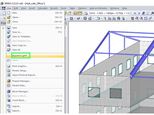
The wind was previously simulated using a model in the wind tunnel. Nowadays, this is much faster, easier, and more efficient. Dlubal Software has also created a digital wind tunnel with RWIND Simulation.
Buildings are structures surrounded by wind. The flow around them creates specific loads on the surfaces. A numerical simulation of wind flows is required to generate wind loads on buildings or other objects. 3D objects are imported, the objects of the environment are added, and the topology is taken into account. Then, the elevation-dependent wind profile and the wind direction are applied. There are results, such as the pressure on the body surface, velocity fields, and streamlines.
Thanks to this progressive development and the many insights from recent years, such tragic events will probably not occur in the future.


.png?mw=350&hash=c6c25b135ffd26af9cd48d77813d2ba5853f936c)


.png?mw=512&hash=ea9bf0ab53a4fb0da5c4ed81d32d53360ab2820c)


.jpg?mw=350&hash=8f312d6c75a747d88bf9d0f5b1038595900b96c1)
