The verification example describes wind loads in several wind directions on a model of a group of buildings. The model consists of eight cubes. The velocity fields obtained by the RWIND simulation are compared with the measured values from the experiment. The experimental data are measured using a thermistor anemometer in the wind tunnel.
Flow Around Simple Group of Buildings
Downloads
Do you have any questions?


Length: 00:00:35 min

Length: 00:01:53 min
Length: 00:00:00 min

Length: 00:00:16 min

Length: 00:02:22 min

Length: 01:05:29 min

Length: 00:00:18 min

Length: 00:01:15 min
Length: 00:58:00 min

.png?mw=350&hash=b023d6c658e181cb7d69028c0f3994dedab96fc5)
,_LC1_LI.jpg?mw=350&hash=871f19dacc172cbb19cbdefc7c490c9db999ca2b)


,_LC1_LI.jpg?mw=350&hash=63fa8f314e69d0e0cb39a37725259712c559d025)
,_LC1__LI.jpg?mw=350&hash=b3482f816b157606c7c88c75bfa2b52c5a8deab0)

Very small torsional moments in the members to be designed often prevent certain design formats. In order to neglect them and still perform the designs, you can define a limit value in RF‑/STEEL EC3 from which torsional shear stresses are taken into account.

This technical article deals with the stability analysis of a roof purlin, which is connected without stiffeners by means of a bolt connection on the lower flange to have a minimum manufacturing effort.

The critical factor for lateral-torsional buckling or the critical buckling moment of a single-span beam will be compared according to different stability analysis methods.

The RF‑/STEEL Warping Torsion module extension of the RF‑/STEEL EC3 add‑on module allows you to design members with asymmetric cross‑sections. The new option is fully integrated in the design module and can be activated for sets of members.


In the ultimate configuration of the steel joint design, you have the option to modify the limit plastic strain for welds.

The "Base Plate" component allows you to design base plate connections with cast-in anchors. In this case, plates, welds, anchorages, and steel-concrete interaction are analyzed.
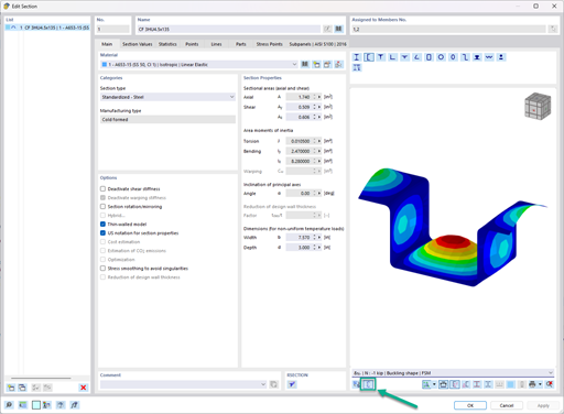
In the "Edit Section" dialog box, you can display the buckling shapes of the Finite Strip Method (FSM) as a 3D graphic.
- Design of five types of seismic force-resisting systems (SFRS) includes Special Moment Frame (SMF), Intermediate Moment Frame (IMF), Ordinary Moment Frame (OMF), Ordinary Concentrically Braced Frame (OCBF), and Special Concentrically Braced Frame (SCBF)
- Ductility check of the width-to thickness ratios for webs and flanges
- Calculation of the required strength and stiffness for stability bracing of beams
- Calculation of the maximum spacing for stability bracing of beams
- Calculation of the required strength at hinge locations for stability bracing of beams
- Calculation of the column required strength with the option to neglect all bending moments, shear, and torsion for overstrength limit state
- Design check of column and brace slenderness ratios
Are the models and presentations from Info Day 2017 freely available, and can you send them to me?
I cannot see any members if the RF‑/STEEL EC3 add-on module is selected as a "load case"; why?
To which axes do the support rotations and support eccentricities in RF‑/STEEL EC3 Warping Torsion refer?
What does the load application point in RF‑/STEEL EC3 Warping Torsion refer to?
What are the options in RFEM 5 or RSTAB 8 for determining the ideal elastic critical moment for lateral-torsional buckling for any cross-sections and systems/loads? Is it also possible to design flat steel (brackets, flat steel stringers of staircases)?
How can I reduce the calculation time for members with a nonlinear material model in RFEM 6 and RSTAB 9?

.jpg?mw=350&hash=91f398b559b26a6ac36fd7ecdf5e395e7b9b856d)


Recommended Products for You
RFEM 6 | Main Program RFEM 6

The new generation of 3D FEA software is used for the structural analysis of members, surfaces, and solids.
Price of First License
4,170.00 USD
RFEM 6 | Additional Analysis
The Form-Finding add-on finds the optimal shape of members subjected to axial forces and tension-loaded surface models. The shape is determined by the equilibrium between the member axial force or the membrane stress and the existing boundary conditions.
Price of First License
2,060.00 USD
RWIND 2 | Stand-Alone

RWIND 2 is a program (digital wind tunnel) for the numerical simulation of wind flows around any building geometries with determination of the wind loads on their surfaces. It can be used as a stand-alone application or used together with RFEM and RSTAB for complete structural analysis and design.
Price of First License
3,080.00 USD
RWIND 2 | Stand-Alone
With RWIND 2, you have a program at your side that uses a digital wind tunnel for the numerical simulation of wind flows.
Price of First License
4,200.00 USD