.svg?mw=64&hash=343d71fbdf234f1411db2920f2dff33c0dbd6231)

Steel Spiral Staircase
| Number of Nodes | 743 |
| Number of Lines | 476 |
| Number of Members | 268 |
| Number of Surfaces | 74 |
| Number of Load Cases | 1 |
| Total Weight | 1.479 tons |
| Dimensions | 20.27 x 20.05 x 22.76 feet |
| Program Version | 5.24.01 |


www.isen_LI.jpg?mw=350&hash=884ca7c4739fd5d2643994f417a345f17b1e1fad)

__LI.jpg?mw=350&hash=313f6f41c5a72a50ce068c38b8e57292d7cc5bd5)


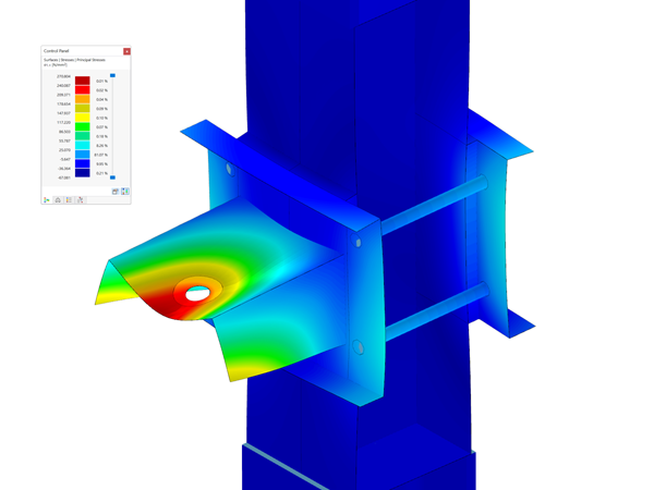
You can display the stress results within members by using clipping planes.

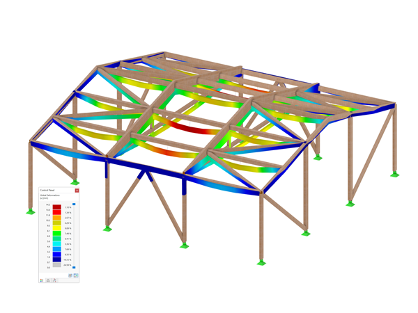
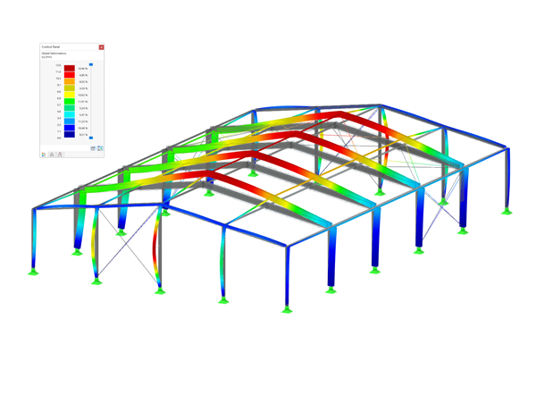
The deformation process of the global deformation components can be represented as a movement sequence.

The results of solid stresses can be displayed as colored 3D points in the finite elements.

Compared to the RF‑/STEEL add-on module (RFEM 5 / RSTAB 8), the following new features have been added to the Stress-Strain Analysis add-on for RFEM 6 / RSTAB 9:
- Treatment of members, surfaces, solids, welds (line welded joints between two and three surfaces with subsequent stress design)
- Output of stresses, stress ratios, stress ranges, and strains
- Limit stress depending on the assigned material or a user-defined input
- Individual specification of the results to be calculated through freely assignable setting types
- Non-modal result details with prepared formula display and additional result display on the cross-section level of members
- Output of the design check formulas used


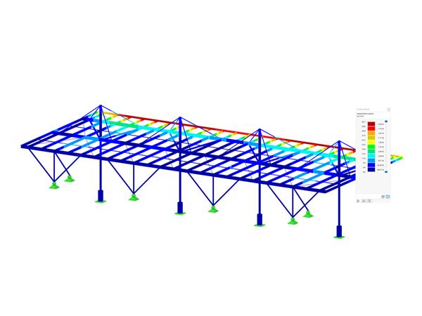
The new generation of 3D FEA software is used for the structural analysis of members, surfaces, and solids.
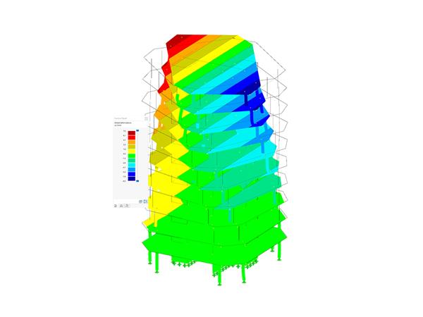
The Structure Stability add-on performs stability analysis of structures. It determines critical load factors and the corresponding stability modes.

The Construction Stages Analysis (CSA) add-on allows for considering the construction process of structures (member, surface, and solid structures) in RFEM.

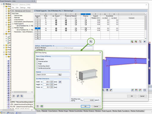
The Torsional Warping (7 DOF) add-on allows you to consider cross-section warping as an additional degree of freedom.

The two-part Optimization & Costs / CO2 Emission Estimation add-on finds suitable parameters for parameterized models and blocks via the artificial intelligence (AI) technique of particle swarm optimization (PSO) for compliance with common optimization criteria. Furthermore, this add-on estimates the model costs or CO2 emissions by specifying unit costs or emissions per material definition for the structural model.
The Stress-Strain Analysis add-on performs general stress analysis by calculating the existing stresses and comparing them with the limit stresses.

The Concrete Design add-on allows for various design checks according to international standards. You can design members, surfaces, and columns, as well as perform punching and deformation analyses.
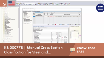
The Steel Design add-on performs the ultimate and serviceability limit state design checks of steel members according to various standards.
The Timber Design add-on performs the ultimate, serviceability, and fire resistance limit state design checks of timber members according to various standards.
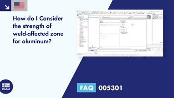
The Aluminum Design add-on performs the ultimate and serviceability limit state design checks of aluminum members according to various standards.
.png?mw=600&hash=49b6a289915d28aa461360f7308b092631b1446e)
The Steel Joints add-on for RFEM allows you to analyze steel connections using an FE model. The FE model is generated automatically in the background and can be controlled via the simple and familiar input of components.

The modern 3D structural analysis and design program is suitable for the structural and dynamic analysis of beam structures as well as the design of concrete, steel, timber, and other materials.
The Structure Stability add-on performs the stability analysis of structures. It determines critical load factors and the corresponding stability modes.
The Torsional Warping (7 DOF) add-on allows for considering cross-section warping as an additional degree of freedom when calculating members.
The Stress-Strain Analysis add-on performs a general stress analysis by calculating the existing stresses and comparing them to the limit stresses.
Concrete Design add-on allows for various design checks of members and columns according to international standards.
The Steel Design add-on performs the ultimate and serviceability limit state design checks of steel members according to various standards.
The Aluminum Design add-on performs the ultimate and serviceability limit state design checks of aluminum members according to various standards.